China Topscom: Testing Technology Research For Pcb Board Assembly.
Keywords: china pcb board industry, pcb board, pcb board assembly, PCBA testing, electronics manufacturing,
pcb assembly, pcba,
0 Overview:
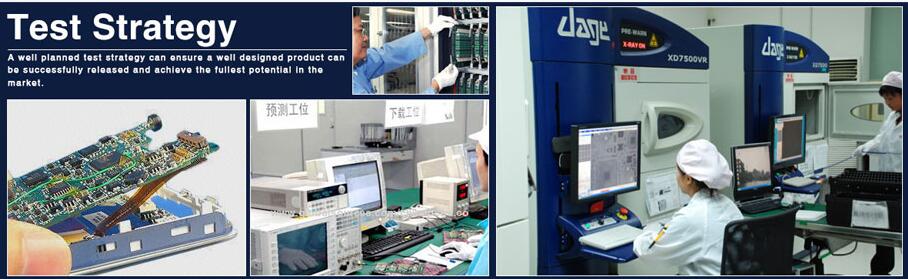
The assembly of pcb boards is one of the basic work of the electronic industry. With the increasing complexity of circuit board assembly technology and the increasing number of batches and varieties of electronic products, it is more and more difficult for circuit board manufacturers to control the assembly quality of pcb boards, and the corresponding testing instruments have become indispensable equipment. In circuit board production enterprises, there are a lot of brake inspection instruments used, so it is inconvenient to discuss them one by one here. This paper only gives a brief introduction to several common batch day testing instruments. I divide the common batch Yong testing instruments into three categories: electrical performance tester, appearance tester and reliability tester.
the article is posted by Mr. Wangjun,director of Topscom SMT Workshop Department,china Topscom provide high difficulty density & printed circuit boards PCB design & layout, mass manufacturing & fabrication,pcba boards assembly,turnkey full systems integration electronic contract manufacturing services.
1 Electrical performance detector:
ICT (on-line tester), MDA (manufacturing defect analysis system) and FCT (function tester) are the three most common types of circuit board assembly electrical performance testing equipment in the market at present, which have some common capabilities and different characteristics.
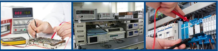
First of all, as testing instruments for electrical performance, they all need to use electrical connection devices, and elastic probes are the most common electrical connectors. Except for individual FCT connectors, ICT, MDA and most FCT are connected by "needle bed".
Both ICT and MDA are fast batch "component level" testing equipment (at present, the body definition of ICT and MDA is somewhat confused at home and abroad. Here, I describe it according to the domestic custom). The defects detected are located to the components. Generally, the testing time of a circuit board is 3Syst60S, and ICT is used for relatively simple circuit board batch testing. It can detect most of the defects of conventional components on the circuit board, such as the values of capacitance, resistance and inductance, the conductivity and direction of the diode, the P value of the transistor, the voltage stabilizing value of the voltage regulator, the short open circuit defects on the circuit board, and so on. With the continuous improvement of ICT equipment, the current ICT equipment can also detect many accessory functions, such as the luminous color of LED and the sensitivity of luminance, MI C. The communication of I / C devices, the action of small power relay and so on. MDA can be considered as a complex ICT,. Usually, MDA can detect the sex of digital IC on-line, which is not available in general ICT equipment. Both ICT and A have their "blind spots" for detection, such as pure parallel capacitors. When small capacitors are missing, it is usually difficult to find them. Of course, those do not affect the performance of electrical appliances.the article is posted by Mr. Wangjun,director of Topscom SMT Workshop Department,china Topscom provide high difficulty density & printed circuit boards PCB design & layout, mass manufacturing & fabrication,pcba boards assembly,turnkey full systems integration electronic contract manufacturing services.
Appearance damage (for example, plastic shell damage) is also difficult to detect.
FCT equipment focuses on testing the overall function of thousands of pairs of pcb boards. In more than 95% of cases, the normal function of the circuit board means the positive of the circuit. Therefore, there are often many products in small batches that only use FCT testing to ensure the production quality of the circuit board. Of course, this is not 100% accurate, for example, the lack of protective devices that only work in extreme cases. Usually it does not necessarily cause abnormal function of the circuit. And once FCT detects the rudiment of the circuit, it can usually only locate the "unit circuit level", but not the components. Therefore, if you want to repair such circuit board faults, you still need a certain level of technology. At present, there are many types of general-purpose FCT. The common G has PIB interface combination instrument type, VXI bus card type, PXI bus card type and VXI bus board card type. They are arranged in turn from simple to complex. Of course, the most widely used and cheapest special-purpose FCT, is often called testing tooling. General instruments are rarely used in such testing tooling. Most of them use "board testing board" to form a complete functional system. One of the pcb boards is replaced by a circuit board that needs to be tested. If the system functions normally, the tested board is "intact". On the contrary, it needs to be repaired or adjusted, and such tooling usually supports manual adjustment of parameters.
2 appearance detector:
The early appearance tester was a magnifying glass or electronic magnifying glass, which was only used to magnify small parts.
The discrimination is still in the human brain. Under such circumstances, the detection speed is very slow, and the personnel are very easy.
Fatigue is also easy to be careless, so people want to detect it automatically.
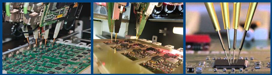
At present, the most common appearance inspection equipment is AOI.. It uses the principle of machine vision to check the appearance of the circuit board, and can detect most of the "visible defects", such as loss and error of components, reverse installation of polarity, short circuit fault, lack of solder and so on. For SMT devices above 10603, AOI can replace manual visual inspection and improve the detection efficiency.
Rate, and for components below 0603, manual visual inspection is no longer possible, can only rely on AOI equipment.
The classification of AOI detection equipment can be divided into different categories from different angles, from the form of cameras, into linear array and area array, from the number of cameras, into single-camera and multi-camera, and from the algorithm used, it can be divided into image contrast type and parameter measurement day type.
The AOI, circuit board motion platform composed of linear camera has only one direction of movement, and the image acquisition of the circuit board is the same as the photocopier, which is scanned at one time. Its advantage is that the scanning speed is fast, and because its light source is usually only fixed in one position, it is difficult to obtain multi-angle light. Therefore, in the details of detection, the line array camera is often not as good as the image collected by the area array CCD camera with the ring light source. The area array camera is composed of AOI.
Linear AOI.
Through the movement of the XY two-dimensional motion platform, the tested circuit board is detected by taking an image one by one, by Qianyou more mechanical movement, compared with the linear array AOI, the detection speed is slightly slower, but the detection accuracy will be higher. According to the number of cameras, AOI is divided into single camera and multi-camera. Here, AOI that splices multiple cameras together to take pictures from one angle is not classified as multi-camera system. Here, multiple cameras refer to AOI systems in which multiple cameras take pictures from multiple different angles. The detection of single-camera system is just like the human eye only observing and detecting from the top of the circuit board.?The lateral lens of the multi-camera system is equivalent to thousands of eyes to observe the circuit board from the side. obviously, only by observing the circuit board from the side can we really detect the "raised feet" of the components. In order to make up for the deficiency of lateral information, the AOI system of single camera often uses multi-angle circular light source to provide multi-angle illumination so as to obtain more lateral visual information. in this way, although it can not completely replace the lateral camera, it can also detect most of the "foot warping" faults.
The camera in AOI is like a human eye, which is used to obtain images, while the software is equivalent to thousands of people's brains. Different software has different special points. At present, AOI can be divided into two main types of software: image contrast type and parameter measurement type. Image contrast AOI is like a person with a very good memory. It has no criteria of right or wrong. Its criteria of right and wrong all come from the results of thousands of "training". The "training" here is to strengthen the memory process, which remembers what is right and what is wrong. Then, when testing, use the results of these training as the standard of right and wrong. The characteristic of this AOI is that it is easy to use, does not require programmers to have a high technical level, and is easy to use. One of its disadvantages is that if the part under test is wrong, it only knows that the result is wrong, but it does not know what the wrong problem is, and another weakness is that it cannot determine good and defect by setting a range of parameters. it needs all kinds of "right" images to train. The only parameter it can set is.
"similarity" is actually the percentage of pixels in the measured map that are the same as the reference image. In many cases, such a percentage does not represent the accuracy of the image under test. For example, the solder day of a solder joint does not state that the solder content is more saturated or closer to the expected value because it is more similar to the "base diagram".the article is posted by Mr. Wangjun,director of Topscom SMT Workshop Department,china Topscom provide high difficulty density & printed circuit boards PCB design & layout, mass manufacturing & fabrication,pcba boards assembly,turnkey full systems integration electronic contract manufacturing services.
Parameter measurement algorithm is commonly used by foreign brands. The disadvantage of parameter measurement AOI is that it has higher skills for programmers.
Skill requires programmers to understand certain optical testing principles. Its advantage is that it can set the standard of "right" and "wrong" without the need of "right" sample or "wrong" sample. When an error is detected, it can also accurately report the type of error, such as lack of tin, multi-tin, false welding and so on. Unlike the image comparison method, it can only report "bad solder joint". The advantage of this is that when using SPC software, the number and location of various fault types can be accurately counted, so as to provide detailed and reliable analysis data for technicians. There are different reasons for the occurrence of "multi-tin" or "lack of tin" at some point.
At present, the "parameter test method" is widely used in foreign AOI, while most domestic AOI brands use "image pair".
Comparison method, Beijing Xinghe AOI uses both algorithms. In the testing of component body, "image comparison method" is mainly used, while regular cutting sites such as thousand solder joints are addressed by "parameters".
Law is the main method, taking into account their respective advantages.
3 Reliability test:
Both ICT and AOI can detect most of the defects of the pcb circuit board, just because of their limitations, the circuit board tested by ICT can only ensure that the circuit components and welding are "good" at that time, while the circuit board tested by AOI can only ensure that the "surface" of the circuit board is "good". They have no ability to detect whether the interior of the solder joint is good or not. To detect the internal quality of solder joints and ensure the long-term reliability of the circuit, we also need the help of a thousand-energy "perspective" instrument-X_RAY detector, also known as AXI.
X_RAY detector uses X-ray perspective imaging principle to check the circuit board. According to its detection accuracy, it is divided into two types: ordinary X_RAY and micro-focus X_RAY with tomographic scanning ability. The former can only use thousands of ordinary solder joints, through the observation of experienced technicians to detect circuit board internal, component internal, and solder joint internal breakage, welding, air bubbles and other faults. The latter, with a finer focus, can form a clearer picture, and then use CT tomography technology to obtain a clear image of each layer of the circuit board, which can urgently build a three-dimensional image and has a more accurate ability to detect the hidden defects in the pcb circuit board.
4 process control:
The above testing equipment, in practical use, can provide the ability to detect a variety of fault phenomena, that is to say, it has a certain ability of "disease detection", but no matter how good the disease is, it is better not to get sick. Therefore, if the process improvement measures can be provided through "disease inspection", it will greatly improve the production of quality equipment. Therefore, each test instrument is equipped with a certain "statistical process control" function software, referred to as SPC. The specific method is to classify and count the fault phenomena obtained from the detection of the testing equipment, and then analyze these classified statistical data to find out the causes of these problems, so as to take measures to eliminate these causes and prevent the occurrence of sinks. to achieve the purpose of preventing defects from the source, for example, on a certain patch circuit board, the "loss rate" of certain packaged devices is very high. The reason is often that there is something wrong with the suction nozzle corresponding to this kind of package. If a solder joint is often "lack of tin", it may be blocked by the corresponding position of the thousand-mesh board, or the design of the solder pad of the circuit board is unreasonable.
(5) the development trend of testing technology:
According to the current technological development, the technical development of future testing equipment mainly has the following directions:
Hello, welcome to visit our official website!
+86 13502814037 (What's up)sales@topscompcbassembly.com

Turnkey Pcba Assembly & Contract Electronic OEM Manufacturing Provider

